
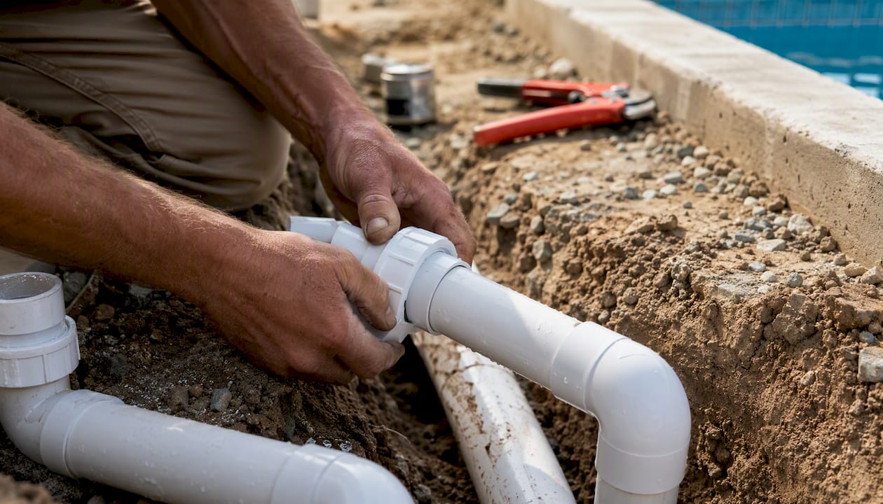
A complete pool plumbing schematic shows every suction outlet (main drains, skimmers, vacuum ports), the full equipment sequence from pump through filter, heater, and sanitizer to return jets, plus valve and union locations, pipe sizes with flow-direction arrows, check valves, and anti-entrapment devices that meet ASME/ANSI A112.19.8 and CPSC/VGB guidance. That’s the minimum a permit-ready pool plumbing diagram must contain before a single trench is dug.
Before you start planning or reviewing any swimming pool plumbing layout, confirm your schematic includes:
- Suction zone: main drain(s) with anti-entrapment cover notation, skimmer(s), and vacuum port(s) with pipe sizes labeled
- Equipment sequence: pump, filter, heater, chemical feeder/sanitizer, in that order, each with isolation unions on both sides
- Return zone: return jet locations, flow-direction arrows, and any dedicated spa or water-feature returns
- Valves: ball valves, actuator valves, check valves, and any diverter valves, each labeled by type and position
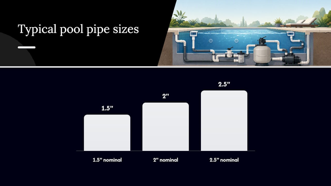
- Pipe sizes: nominal diameter called out on every run (1.5", 2", or 2.5" are most common)
- Safety notations: ASME/ANSI A112.19.8-compliant drain cover specs, dual-drain or unblockable-drain confirmation, and SVRS or equivalent anti-entrapment system noted per the International Swimming Pool and Spa Code (ISPSC)
- Inspection notes: pre-backfill pressure-test requirement and AHJ hold-point callouts
If any of those elements is missing from your diagram, the schematic isn’t ready for permit submission or contractor handoff. Ag-plumbing produces permit-ready pool plumbing schematics and handles full installation for homeowners and contractors in the Pittsburgh area.
Key Takeaways
A complete, permit-ready pool plumbing schematic must show every suction outlet, the full equipment sequence with unions, pipe sizes with flow arrows, and documented anti-entrapment compliance before any trench is backfilled.
| Point | Details |
|---|---|
| Label every element | Schematic must show suction outlets, equipment sequence, return jets, valve types, pipe sizes, and anti-entrapment system. |
| Size pipe generously | 1.5" handles Moderate flow, 2" handles Higher flow, 2.5" handles Large pool flow; upsize for long runs or variable-speed pumps. |
| Unions at every component | Install unions on both sides of pump, filter, heater, and feeder so components can be removed without cutting pipe. |
| Pressure-test before backfill | Test buried lines to at least 30 psi for 30 minutes and document the result before covering any trench. |
| Ag-plumbing for turnkey help | Ag-plumbing produces permit-ready schematics and handles full pool plumbing installation in the Pittsburgh area. |
Table of Contents
- What do common pool plumbing schematics look like?
- How to read a pool plumbing schematic: symbols and flow arrows
- What materials and pipe sizes does pool plumbing use?
- Design principles: how do you lay out a pool pipe system?
- What safety codes apply to pool plumbing and main drains?
- How do schematics change for solar heaters, spa jets, and chemical feeders?
- What tools and templates help you draw a pool plumbing schematic?
- When should you hire a pro instead of DIYing the schematic or install?
- What 30 years of pool plumbing work actually teaches you
- Ag-plumbing produces permit-ready pool plumbing diagrams and handles full installation
- Primary sources and references
- Sources
- FAQ
What do common pool plumbing schematics look like?
The table below maps the six most common pool plumbing diagram types to their key elements, so you can find the layout that matches your project and use it as a starting template.
| Schematic Type | Primary Use Case | Key Elements Shown |
|---|---|---|
| Single-pump residential | Standard in-ground pool, one circulation pump | Skimmer, main drain, pump, filter, heater, return jets, isolation valves, unions |
| Pool + spa combo (shared pump) | Pool and spa on one circulation loop with diverter valve | Diverter valve bank, spa jets, spillover return, check valves, shared heater |
| Pool + spa (separate pumps) | High-performance or large-volume installations | Two pump pads, dedicated suction/return for spa, actuator valve control |
| Solar heating bypass loop | Solar panel array added to existing pool system | Solar panels, bypass valve, check valve, throttling valve, temperature sensor taps |
| Two-pump with chemical feeder | Pool with dedicated booster or cleaner pump plus inline feeder | Salt cell or ozone/UV unit after filter, chemical feeder bypass union, second pump branch |
| Water feature / jet pump | Deck jets, waterfalls, or raised spa with separate pump | Dedicated jet pump, separate suction stub, return manifold, isolation valve |
Each of these pool plumbing diagram types follows the same hydraulic sequence: suction to pump to filter to heater to sanitizer to return. The differences show up in how many suction branches feed the pump, how many return zones exist, and how bypass loops are routed around the heater or solar array.
Pro Tip: Save a PDF copy of the schematic type that matches your pool before your permit meeting. Many AHJs accept a clearly labeled diagram as a supplement to the permit application, and having it in hand speeds the review.
How to read a pool plumbing schematic: symbols and flow arrows
Pool plumbing diagrams use a small set of recurring symbols. Once you know them, any schematic becomes readable in a few minutes.
Standard symbol reference:
- Skimmer: rectangle with a dashed suction line leading to the main header; usually labeled “SK-1,” “SK-2”
- Main drain: circle or square at pool floor, often with “MD” and a note referencing the anti-entrapment cover model
- Pump: circle with an impeller arrow, labeled with horsepower and model number on permit drawings
- Filter: cylinder or tank symbol, labeled with filter type (sand, cartridge, DE) and flow rate
- Heater: rectangle with flame or coil symbol, labeled with BTU rating and fuel type
- Chemical feeder / salt cell: inline rectangle, positioned after the filter and before the return
- Check valve: arrow-in-circle or half-moon symbol; flow passes one direction only
- Ball valve / actuator valve: filled square or circle on the pipe line; actuator valves get an “A” designation
- Union: two parallel lines crossing the pipe; marks a service-removable joint
- Cleanout / vacuum port: tee fitting with a cap symbol, labeled “VP” or “CO”
Line types tell you where pipe runs:
Solid lines show above-grade or visible pipe. Dashed lines indicate buried or concealed runs. Thick lines typically represent pressure-side (return) pipe; thinner lines show suction-side runs. Flow-direction arrows sit on the line itself, pointing from suction toward the pump and from the pump toward the returns.
A well-drawn pool plumbing diagram also notes pipe slope. Any run that could trap water in a freeze climate should slope at least 1/8 inch per foot toward a drain point, and that slope is usually annotated directly on the buried-run dashed line.
What materials and pipe sizes does pool plumbing use?
Schedule 40 PVC is the baseline
Schedule 40 PVC is the standard material for residential pool plumbing. It handles the pressure ranges a typical pool pump produces, bonds reliably with solvent cement, and is widely available. Schedule 80 PVC steps in for high-stress points: threaded connections at the pump, manifold sections under sustained vibration, and any run that sees mechanical impact. CPVC replaces PVC within roughly 18–24 inches downstream of a gas heater, where sustained heat would soften standard PVC over time.
Flex PVC is common on short stub connections between rigid runs and equipment because it absorbs vibration and simplifies alignment. For long buried runs, rigid PVC is more durable and less prone to kinking or collapsing under soil load. Avoid ABS and metal fittings in pool environments; both corrode or react with pool chemistry faster than PVC.
For above-grade runs exposed to sunlight, UV degradation and freeze damage are the two leading failure modes. Wrap or paint exposed PVC with UV-blocking pipe wrap, and slope every above-grade run so it drains completely before a freeze.
Pipe sizing and flow capacity
| Pipe Diameter | Approximate Max Flow | Typical Application |
|---|---|---|
| 1.5" Schedule 40 PVC | Moderate flow | Skimmer suction lines, small return branches |
| 2" Schedule 40 PVC | Higher flow | Main suction header, primary return header |
| 2.5" Schedule 40 PVC | Large pool flow | High-flow main drain headers, large pool returns |
Bigger pipe reduces friction loss, which means the pump works less hard for the same flow rate. Pair oversized pipe with a variable-speed pump and you can run at lower RPM for the same turnover time, cutting energy use noticeably. That’s not a theoretical benefit; it’s the reason most energy-conscious pool builds now spec 2" or 2.5" headers even on modest residential pools.
Pro Tip: When sizing pipe for a new build, go one size larger than the minimum the pump requires. The pipe is cheap; the energy savings over the pump’s lifespan are not.
Pipe sizing at a glance: 1.5" handles moderate flow, 2" supports higher flow rates, and 2.5" accommodates large pool flows. Size up whenever the run is long or the pump is variable-speed.
Fittings rules that matter:
- Install unions on both sides of every piece of equipment (pump, filter, heater, feeder). Glued joints at service points mean cutting pipe every time a component needs replacement.
- Use a thermal break of 18–24 inches of CPVC or a listed flexible connector immediately downstream of a gas heater before transitioning back to PVC.
- Support rigid PVC every 4–6 feet horizontally and at every change of direction to prevent sag and joint stress.
- Pipe and fittings must be listed and labeled per the applicable model plumbing code, so confirm NSF/ASTM markings on any pipe you purchase.
Design principles: how do you lay out a pool pipe system?
Good pool plumbing design starts with hydraulics, not aesthetics. The goal is to move water from every suction point through the equipment train and back to every return with the least friction and the most serviceability.
Core layout principles
Keep suction runs as short and straight as possible. Every elbow and every foot of pipe adds resistance the pump must overcome. Centralizing the equipment pad relative to the pool cuts average pipe run length and balances suction across multiple inlets.
Separate suction and return zones so that filtered, treated water doesn’t short-circuit back to the pump before it circulates the full pool volume. Returns placed on the opposite end of the pool from skimmers create a full-pool circulation path.
Isolation valves before and after every major component let you shut down one piece of equipment without draining the system. Pair them with unions so the component lifts out cleanly. Shutoff valves at key service points are one of the most practical investments in a pool plumbing design.
For pump sizing, calculate total dynamic head (TDH) and plot it against the pump’s performance curve. Select the smallest pump that meets your turnover requirement at that TDH. Oversized pumps run at the wrong point on their curve, waste energy, and wear out faster. Variable-speed pumps let you dial back RPM during off-peak hours, which is where most of the energy savings come from.
Pre-install checklist
Follow these steps in order before backfilling any trench:
- Lay out trench routes and confirm minimum burial depth per local code (typically 12–18 inches for pool pipe).
- Verify main drain placement: dual drains must be at least 3 feet apart (center to center) or replaced with a single unblockable drain meeting ASME/ANSI A112.19.8.
- Confirm skimmer count and placement relative to prevailing wind and return jet direction.
- Dry-fit all pipe runs before solvent-welding; check alignment at every equipment connection.
- Pressure-test all buried lines to at least 30 psi for a minimum of 30 minutes before backfilling. Document the test with a written record.
- Install anti-entrapment drain covers and confirm the cover’s flow rating equals or exceeds the installed pump’s maximum flow.
- Schedule the AHJ concealed-piping inspection before backfill; pre-backfill inspection is a standard hold point in most jurisdictions.
What safety codes apply to pool plumbing and main drains?
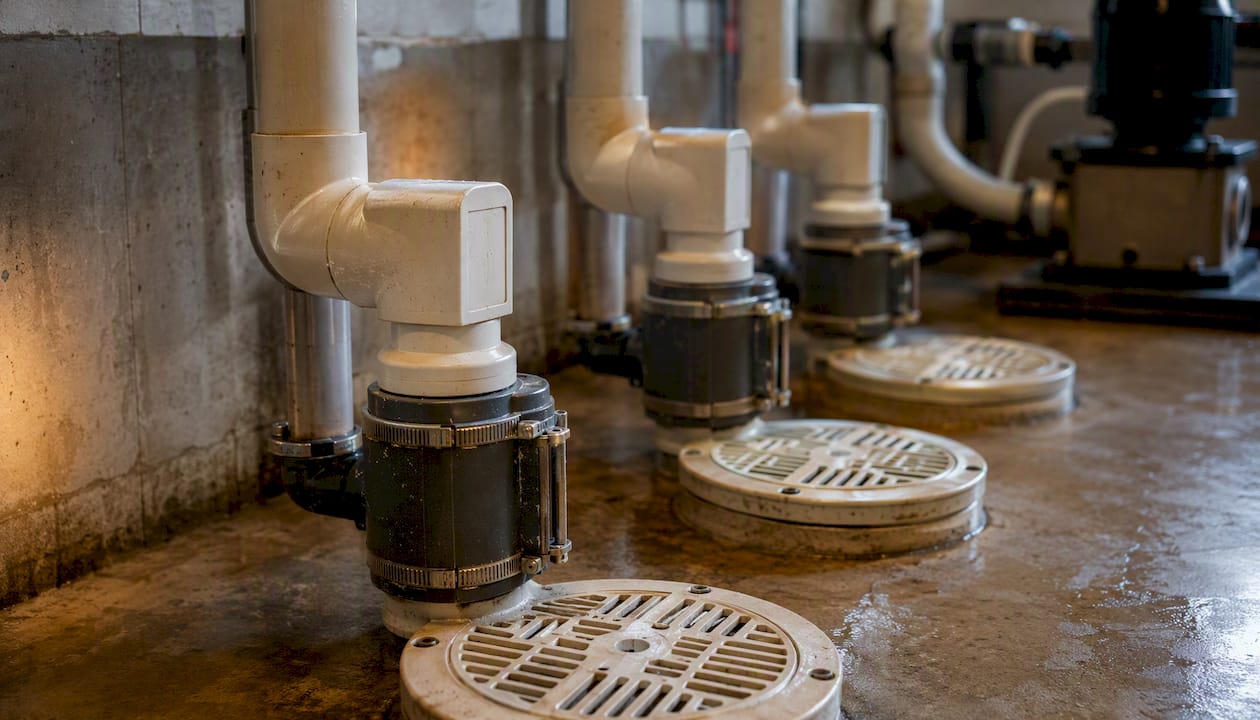
Anti-entrapment compliance is the non-negotiable safety item in any pool plumbing diagram. The Virginia Graeme Baker Pool and Spa Safety Act (VGB Act), codified at 15 U.S.C. §8003, requires public pools and spas to use drain covers that meet ASME/ANSI A112.19.8 and to install at least one of the following anti-entrapment systems:
| Anti-Entrapment System | How It Works | Notes |
|---|---|---|
| SVRS (Safety Vacuum Release System) | Detects suction blockage and shuts pump or reverses flow within seconds | Must meet ASME/ANSI A112.19.8 |
| Suction-limiting vent system | Limits vacuum at the drain if blocked | Passive; no power required |
| Gravity drainage system | Drains the pool by gravity if suction is blocked | Requires specific tank/sump design |
| Automatic pump shut-off | Shuts pump on blockage detection | Sensor-based; requires power |
| Drain disablement | Permanently disables the main drain suction | Skimmer-only circulation; reduces flexibility |
The CPSC staff interpretation clarifies definitions for “unblockable drain” and multi-drain configurations. A single drain is unblockable if its open area is large enough that a body cannot seal it; dual drains qualify when spaced at least 3 feet apart (center to center) and plumbed to a common suction line so neither can be fully blocked alone.
Pro Tip: Mark the anti-entrapment system type and the drain cover model number directly on your schematic. Inspectors look for it, and having it on the drawing saves a separate documentation step at inspection.
Residential pools are governed by state and local codes that often adopt the ISPSC, which references the same ASME/ANSI standards. Always confirm which edition your AHJ has adopted before finalizing your design.
How do schematics change for solar heaters, spa jets, and chemical feeders?
Add-ons each require their own plumbing branch, and each branch introduces potential conflicts if not planned carefully.
Solar heating bypass loop:
- A dedicated bypass line with a throttling valve and a check valve routes water through the solar panels when they’re warmer than the pool.
- The check valve prevents reverse thermosiphon flow at night, which would cool the pool.
- Show the bypass ratio (what fraction of flow goes through panels vs. bypassing them) as a note on the schematic; it helps with future balancing.
- Solar panels sit after the filter and before the heater in the equipment sequence, so filtered water enters the panels.
Chemical feeders, salt cells, UV, and ozone:
- All chemical injection points belong after the filter and before the return, never before the pump or filter where chemistry could damage equipment.
- Install unions and a bypass loop around the feeder so it can be serviced without shutting down the entire system.
- UV and ozone units require electrical coordination; note the power source and any required bonding connections on the schematic.
- Salt cells need a minimum flow rate to function correctly; confirm the cell’s minimum gpm against your pump’s low-speed output.
Spa combinations and two-pump setups:
- A shared-pump pool/spa system uses a diverter valve bank to redirect suction and return between pool and spa modes. Show each valve position (pool mode vs. spa mode) as a separate callout or a mode-state table on the schematic.
- When spa jet demand exceeds what the circulation pump can deliver, a dedicated jet pump on its own suction and return circuit is the cleaner solution. Two separate pumps mean two separate suction branches, two sets of isolation valves, and two return manifolds, all of which need to appear on the pool spa plumbing diagram.
- Actuator valves controlled by an automation system should be noted with their actuator model and the control wire run shown as a dashed electrical line on the schematic.
What tools and templates help you draw a pool plumbing schematic?
You don’t need professional CAD software to produce a usable pool plumbing diagram, but you do need a consistent symbol set and clear labeling.
- Printable PDF templates: Several pool supply and training sites offer blank pool plumbing layout templates with pre-drawn equipment symbols. Download one, print at 11" x 17" for legibility, and sketch your pipe runs by hand. These work well for permit supplements when the AHJ doesn’t require engineered drawings.
- Diagramming apps (Lucidchart, draw.io): Both offer free tiers with shape libraries you can customize for pool symbols. Export as PDF for permit submission or share a link with your contractor for review.
- ArcSite and field-sketching apps: ArcSite and similar mobile apps let you photograph the equipment pad, annotate pipe runs directly on the photo, and export a dimensioned PDF. Useful for as-built documentation after installation.
- CAD (AutoCAD LT, LibreCAD): Required for engineered permit drawings in some jurisdictions. If your AHJ requires a licensed engineer’s stamp, the drawing will need to originate in a CAD platform regardless of what you sketch first.
What every schematic must label:
- Pipe diameter on every run segment
- Flow-direction arrows on every line
- Valve type and normal operating position (open/closed)
- Union locations (mark with “U” or the standard union symbol)
- Equipment model and serial number (required for permit drawings in most jurisdictions)
- Pipe material and schedule on buried runs
- Slope notation on any run in a freeze climate
- Anti-entrapment system type and drain cover model
Drafting tips for a permit-ready drawing:
- Use separate layers or line weights for suction (thin), return (thick), and electrical (dashed) runs so the diagram reads clearly in black-and-white print.
- Annotate stub-out lengths at equipment unions so the next technician knows how much pipe to expect.
- Attach a commissioning checklist as a second page: pressure test result, cover flow rating confirmation, and AHJ inspection date.
- Labeled diagrams speed future repairs significantly; a schematic that lives in the equipment room is worth more than one filed in a drawer.
When should you hire a pro instead of DIYing the schematic or install?
A schematic you draw yourself is a planning tool. Whether it becomes a permit document depends on your jurisdiction and the complexity of the system.
DIY is reasonable for: sketching a layout to brief a contractor, understanding what your existing system contains, or producing a supplemental diagram for a simple single-pump residential pool in a jurisdiction that accepts homeowner-drawn supplements.
Hire a licensed contractor when any of the following apply:
- Your AHJ requires a licensed plumber or engineer to sign permit drawings.
- The project involves buried trenching, which triggers inspection hold points and liability if pipe fails under backfill.
- Main-drain anti-entrapment compliance is in question; getting this wrong carries serious safety and legal consequences.
- The system includes a gas heater, salt cell, or automation controller, where electrical and plumbing coordination is required.
- You’re adding a spa, solar loop, or second pump to an existing system, where hydraulic balancing affects the whole circulation loop.
A licensed contractor will produce permit drawings with TDH calculations, perform a witnessed pressure test, coordinate the AHJ concealed-piping inspection, and provide documentation for the pre-plaster or pre-liner inspection. That paper trail protects you at resale and during any insurance claim.
Ag-plumbing handles permit-ready pool plumbing schematics and full installation for homeowners and contractors. Contact Ag-plumbing to discuss your project scope before you commit to a design.
What 30 years of pool plumbing work actually teaches you
Most pool plumbing problems I see in the field trace back to one of two decisions made at the design stage: pipe that’s too small for the pump installed, or a schematic that was never drawn at all.
When there’s no diagram, every service call starts with a detective exercise. Which valve controls which branch? Where does this line go? Is that a suction or return? A labeled pool plumbing diagram in the equipment room cuts that guesswork immediately. Research on plumbing schematics consistently shows that documented systems get diagnosed and repaired faster than undocumented ones, and pool systems are no exception.
The second pattern is oversized pumps paired with undersized pipe. A 2 HP pump pushing through 1.5" suction lines creates velocity noise, accelerated fitting wear, and a pump that runs at the wrong point on its curve. The fix at that stage costs far more than specifying 2" pipe from the start. Variable-speed pumps help, but they can’t fully compensate for a pipe system that was never sized correctly.
The third thing experience teaches: anti-entrapment compliance isn’t a checkbox. It’s the item that, if missed, carries the most serious consequences of anything in a pool build. Every schematic Ag-plumbing produces includes the drain cover model, the anti-entrapment system type, and the flow rating confirmation, because those three items are what an inspector looks for and what protects the homeowner long after the pool is filled.
Ag-plumbing produces permit-ready pool plumbing diagrams and handles full installation
Producing a pool plumbing schematic that passes permit review takes more than a sketch. It requires accurate pipe sizing, TDH calculations, anti-entrapment documentation, and coordination with your local AHJ. That’s exactly what Ag-plumbing delivers, backed by 30 years of plumbing experience in Pittsburgh and the surrounding region.
Ag-plumbing’s pool plumbing service includes on-site measurement, a permit-ready CAD or printable schematic, a pressure-test report, and AHJ inspection coordination from rough-in through final sign-off. Whether you’re building a new in-ground pool, adding a spa, or retrofitting a solar loop, the team handles the full scope so you’re not managing three separate contractors. See the full range of plumbing services Ag-plumbing offers, or reach out directly to get a quote for your pool plumbing project.
Primary sources and references
These are the primary standards and resources cited in this article. Verify which edition your local AHJ has adopted before finalizing any design.
- CPSC Staff Interpretation (Pool & Spa Safety Act) — Defines unblockable drains, multi-drain configurations, and acceptable anti-entrapment systems (SVRS, suction-limiting vent, gravity drainage, automatic shut-off, drain disablement).
- ICC Section 302 sample (ISPSC plumbing requirements) — Model code language for pool/spa plumbing, pipe listing/labeling requirements, and pre-backfill concealed-piping inspection hold points.
- Pipe Materials and Fittings — Florida’s Best Pools — Practical pipe-sizing guidance (gpm by diameter), Schedule 40/80/CPVC selection, and UV/freeze failure modes.
- Pool Plumbing Configuration and Service Points — PoolTechResources — Hydraulic sequence overview, common configurations, and service-point documentation guidance.
- Pool Plumbing Installation — Pool Installer Authority — Installer step sequence, inspection hold points, and pressure-testing standards.
Always confirm the adopted code edition with your authority having jurisdiction (AHJ) before finalizing any pool plumbing design.
Sources
- CPSC Staff Interpretation (Pool & Spa Safety Act)
- ICC sample: Section 302—Electrical, plumbing, mechanical and fuel gas requirements (sample)
- Pipe Materials and Fittings (PVC, CPVC, Corrosion-Resistant) — Florida’s Best Pools
- Pool Plumbing Configuration and Service Points — PoolTechResources
FAQ
What is a schematic for pool plumbing?
A pool plumbing schematic is a labeled diagram showing every suction outlet, the pump-filter-heater-sanitizer equipment sequence, return jet locations, valve and union positions, pipe sizes, flow-direction arrows, and anti-entrapment device notations. It serves as both a planning document and a permit submission supplement.
How are pool pipes connected?
Pool pipes are connected primarily with solvent-welded (glued) Schedule 40 PVC fittings for permanent buried runs, and with threaded or union connections at equipment so components can be removed for service without cutting pipe.
Can I use Schedule 40 PVC for pool plumbing?
Yes. Schedule 40 PVC is the standard baseline material for residential pool plumbing. Step up to Schedule 80 at threaded connections and high-stress points, and use CPVC for the 18–24 inches immediately downstream of a gas heater where sustained heat would soften standard PVC.
How are pool drains plumbed?
Main drains connect via a dedicated suction line to the pump’s suction header. Dual drains must be spaced at least 3 feet apart (center to center) and plumbed to a common suction pipe so neither can be fully blocked alone, satisfying the anti-entrapment requirements under ASME/ANSI A112.19.8 and the VGB Act.
When do I need a professional to produce my pool plumbing diagram?
Hire a licensed contractor when your AHJ requires a signed permit drawing, when the project involves buried trenching or a gas heater, or when anti-entrapment compliance is in question. Ag-plumbing produces permit-ready pool plumbing schematics with pressure-test documentation and full AHJ coordination.
Recommended
- Emergency Plumbing Guide: Quick Solutions for Homeowners – AG-Plumbing
- Plumbing troubleshooting: Steps to fix common issues – AG-Plumbing
